EC2: Bending with or without axial force
6.1 Bending with or without axial force
(1)P This section applies to undisturbed regions of beanls, slabs and similar types of members for which sections remain approximately plane before and after loading. The discontinuity regions of beams and other members in which plane sections do not remain plane may be designed and detailed according to 6.5.
(2)P When determining the ultinlate moment resistance of reinforced or prestressed concrete cross-sections, the following assumptions are made:
- plane sections remain plane.
- the strain in bonded reinforcement or bonded prestressing tendons, whether in tension or in compression, is the same as that in the surrounding concrete.
- the tensile strength of the concrete is ignored.
- the stresses in the concrete in compression are derived from the design stress/strain relationship given in 3.1.7.
- the stresses in the reinforcing or prestressing steel are derived from the design curves in 3.2 (Figure 3.8) and 3.3 (Figure 3.10).
- the initial strain in prestressing tendons is taken into account when assessing the stresses in the tendons.
(3)P The compressive strain in the concrete shall be limited to εcu2, or εcu3, depending on the stress-strain diagram used, see 3.1.7 and Table 3.1. The strains in the reinforcing steel and the prestressing steel shall be limited to εud (where applicable); see 3.2.7 (2) and 3.3.6 (7) respectively.
(4) For cross-sections loaded by the compression force it is necessary to assume the minimum eccentricity, eo = h/30 but not less than 20 mm where h is the depth of the section.
5) In parts of cross-sections which are subjected to approximately concentric loading (ed/h ≤ 0,1), such as compression flanges of box girders, the mean compressive strain in that part of the section should be limited to εc2 (or εc3 if the bilinear relation of Figure 3.4 is used)
(6) The possible range of strain distributions is shown in Figure 6.1.
(7) For prestressed members with permanently unbonded tendons see 5.10.8.
(8) For external prestressing tendons the strain in the prestressing steel between two subsequent contact points (anchors or deviation saddles) is assumed to be constant. The strain in the prestressing steel is then equal to the initial strain, realised just after completion of the prestressing operation, increased by the strain resulting from the structural deformation between the contact areas considered. See also 5.10.
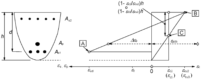
A- reinforcing steel tension strain limit
B - concrete compression strain limit
C - concrete pure compression strain limit
Figure 6.1: Possible strain distributions in the ultimate limit state
3.1 Concrete
3.1.7 Stress-strain relations for the design of cross-sections
(2) Other simplified stress-strain relationships may be used if equivalent to or more conservative than the one defined in (1), for instance bi-linear according to Figure 3.4 (compressive stress and shortening strain shown as absolute values) with values of εc3 and εcu3 according to Table 3.1.
εc3(0/00) = 1.75 for fck ≤ 50 MPa
εc3(0/00) = 1,75 + 0,55[(fck - 50)/40] for 50 < fck ≤ 90 MPa
and
εcu3(0/00) = 3.50 for fck ≤ 50 MPa
εcu3(0/00) = 2.6 + 35[(90 - fck)/100]4 for 50 < fck ≤ 90 MPa
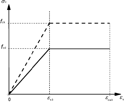
Figure 3.4: Bi-linear stress-strain relation.
(3) A rectangular stress distribution (as given in Figure 3.5) may be assumed. The factor λ, defining the effective height of the compression zone and the factor η, defining the effective strength, follow from:
and
Note: If the width of the compression zone decreases in the direction of the extreme compression fibre, the value η·fcd should be reduced by 10%.
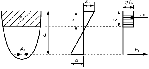
Figure 3.5: Rectangular stress distribution
3.2 Reinforcing steel
3.2.7 Design assumptions
(2) For normal design, the following assumptions may be made (see Figure 3.8):
- a) an inclined top branch with a strain limit of εud and a maximum stress of k·fyk/γs, where k= (ft/fy)k;
Note 1: The value of εud for use in a Country may be found in its National Annex. The recommended value is 0.90·εuk
Note 2: The value of (ft/fy)k is given in Annex C (table C1).
Table C.1: Properties of reinforcement
| Bars and de-coiled rods | |||
| Class | A | B | C |
| Characteristic yield strength fyk or f0,2k (MPa) | 400 a 600 | ||
| Minimum value of k = (ft/fy)k | ≥ 1,05 | ≥ 1,08 | ≥ 1,15 |
| Characteristic strain at maximum force, εuk (%) | ≥ 2,5 | ≥ 5,0 | ≥ 7,5 |
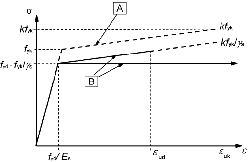
A- Idealised; B- Design
Figure 3.8: Idealised and design stress-strain diagrams for reinforcing steel (for
tension and compression)
(3) The mean value of density may be assumed to be 7850 kg/m3.
(4) The design value of the modulus of elasticity, Es may be assumed to be 200 GPa.
Strain envelopes
The limit stains in sections, depending on the type of stress, enable the following ranges to be recognised:
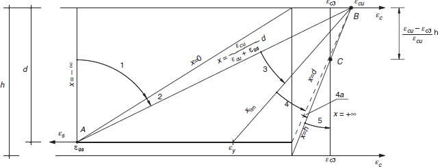
- Range 1: Pure or combined tension where the entire section is under tension. The strain lines turn about point A corresponding to an elongation in the reinforcement of the most tensioned of εud.
- Range 2: Pure or combined bending, in which the concrete does not reach the ultimate bending strain. The strain lines turn about point A.
- Range 3: Pure or combined bending, in which the strain lines turn about point B corresponding to the ultimate bending strain of the concrete εcu3 defined in paragraph 3.1.7. The elongation of the most tensioned reinforcement is between εud and εy (the elongation corresponding to the yield stress of the steel).
- Range 4: Single or combined bending in which the strain lines turn around point B. The elongation of the most tensioned reinforcement is between εy and 0.
- Range 4a: Combined bending in which all the reinforcements are compressed and where there is a small area of concrete in tension. The strain lines turn about point B.
- Range 5: Single or combined compression in which both materials are in compression. The strain lines turn about point C, as defined by the line corresponding to the ultimate compression strain of concrete, εc3, defined in paragraph 3.1.7.
The neutral axis "x" is an axis in the cross section which there are no longitudinal stresses or strains.
Deformation ranges correspond to all combinations of bending and axial force, from simple tensile to the simple compression, by varying the depth of the neutral axis "x" from - ∞ to + ∞ .
Checking rectangular sections
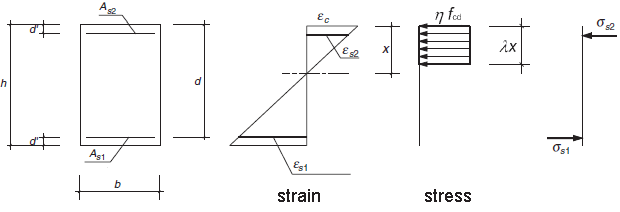
The equilibrium equations that determine the bending and axial force at failure (Mu and Nu) are the following
(Interaction diagram between axial load Ν and bending moment M)
Range 1:
- ∞ < x ≤ 0
- Nu(x) = - As2·σs2[εs2] - As1·σs1[εud]
- Mu (x)= - As2·σs2[εs2]·(h/2-d') - As1·σs1[εud]·(h/2-d)
- εs2(x) = εud·(d'-x)/(d-x)
Range 2:
0 < x ≤ d · εcu/(εcu+εud)
- Nu(x) = η·fcd·λ·x·b + As2·σs2[εs2] - As1·σs1[εud]
- Mu(x)= η·fcd·λ·x·b·(h/2-λ·x/2) + As2·σs2[εs2]·(h/2-d') - As1·σs1[εud]·(h/2-d)
- εs2(x) = εud·(x-d')/(d-x)
Range 3:
d · εcu/(εcu+εud) < x ≤ xlim
- Nu(x) = η·fcd·λ·x·b + As2·σs2[εs2] - As1·σs1[εs1]
- Mu(x) = η·fcd·λ·x·b·(h/2-λ·x/2) + As2·σs2[εs2]·(h/2-d') - As1·σs1[εs1]·(h/2-d)
- εs2(x) = εcu·(x-d')/x
- εs1(x) = εcu·(d-x)/x
Range 4:
xlim< x ≤ d
- Nu(x) = η·fcd·λ·x·b + As2·σs2[εs2] - As1·σs1[εs1]
- Mu(x) = η·fcd·λ·x·b·(h/2-λ·x/2) + As2·σs2[εs2]·(h/2-d') - As1·σs1[εs1]·(h/2-d)
- εs2(x) = εcu·(x-d')/x
- εs1(x) = εcu·(d-x)/x
Range 4a:
d < x ≤ h
- Nu(x) = η·fcd·λ·x·b + As2·σs2[εs2] + As1·σs1[εs1]
- Mu/x) = η·fcd·λ·x·b·(h/2-λ·x/2) + As2·σs2[εs2]·(h/2-d') + As1·σs1[εs1]·(h/2-d)
- εs2(x) = εcu·(x-d')/x
- εs1(x) = εcu·(x-d)/x
Range 5:
h < x < ∞
- Nu(x) = η·fcd·[1- (1-λ)·h/x]·h·b + As2·σs2[εs2] + As1·σs1[εs1]
- Mu(x) = η·fcd·[1- (1-λ)·h/x]·h·b·[h/2-[1- (1-λ)·h/x]·h/2] + As2·σs2[εs2]·(h/2-d') + As1·σs1[εs1]·(h/2-d)
- εs2(x) = εc3·(x-d')/(x-h/2)
- εs1(x) = εc3·(x-d)/(x-h/2)


